Inductance Analyzers - 3255BL 3255B 3255BQ | |||||||||||||||||||||||||||||||||||||||||||||||||||||||||||||||||||||||||||||||||||||||||||||||||||||||||||||||||||||||||||||||||||||||||||||||||||
 |
| ||||||||||||||||||||||||||||||||||||||||||||||||||||||||||||||||||||||||||||||||||||||||||||||||||||||||||||||||||||||||||||||||||||||||||||||||||
| Prospekt | |||||||||||||||||||||||||||||||||||||||||||||||||||||||||||||||||||||||||||||||||||||||||||||||||||||||||||||||||||||||||||||||||||||||||||||||||||
|
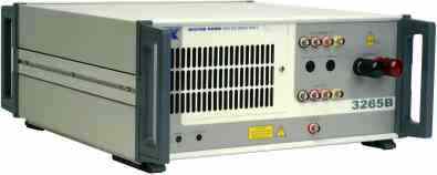
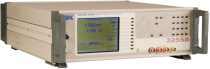
3255B and 3255BQ are highly versatile and accurate inductance analyzers able to characterise devices in a clear and simple manner. The three models in the range are the 3255BL (200kHz), 3255B (500 kHz) and the 3255BQ (1 MHz). At the design stage of component development it is very important to analyse how components performs under different operating conditions. This includes operation over a range of frequencies, AC drive levels or DC bias currents. The AC drive level can be set between 1 mV to 10 V. DC bias current can be set from 1 mA to 1 A internally (optional) with external DC bias units available increasing the maximum current to 125 A (3255B and 3255BQ). Specification summary
Printed output of test resultsUsing the parallel Centronics interface the user can directly print all test results for further analysis and archiving. In addition, via the optional GPIB interface, the instrument can be controlled from a PC and results can be read back for analysis and storage. LabVIEW™ drivers are available upon request or may be downloaded from this website providing a base from which a user can develop a specific test application. Bin sortThe binning function allows component manufacturers to sort components in up to ten bins. Sorting is carried out either by absolute values or by percentage of values. Component tests with up to 125 A DC bias current
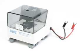
3265B/25A DC Bias Unit can deliver up to 25 A of DC bias current in steps of 0.025 A The 3255B and 3255BQ enable components to be measured at up to 125 A when multiple external 3265B/25A DC Bias units are used. Extended DC bias capability is also available with the 3255BL which uses the 3265B/5A or 3265B/10A to extend the DC bias current available to 50A. Up to five of the DC Bias Units can be used in parallel to give a wide range of DC bias currents. The 3255B Inductance Analyzer can optionally provide an internal DC bias from 1 mA to 1 A. The 3265B has a number of safety and protection features including a safety interlock system to protect users against back EMFs. It is also fully protected against over temperature, excess voltage drop and sense lead failure. SMD inductor tests up to 50 A
1009 DC Bias Fixture enables currents up to 50 A to be applied to an SMD inductor With the addition of the 1009 DC Bias Fixture DC bias currents up to 50 A can be applied to an SMD inductor during component test in order to evaluate the devices thoroughly at the operational bias currents. The fixture operates with either one or two 3265B/25A Wayne Kerr DC bias units and a 3255B Inductance Analyzer. If two 3265B/25As are used then the optional 5-328-2005 high current lead set will be required. Four rear panel mounted BNC connectors and two captive high current cables ensure simplicity and ease of use with the 3265B. Interchangeable component test carriers ensure that the 1009 DC Bias Fixture may be used with a wide variety of devices. If a device package is not supported by one of the standard carriers then a custom carrier design service is available. Stable component fixturing ensures high accuracy and repeatable measurements. Enclosed fixtures, with safety interlocks, minimises risk to operators. Technical specificationsOperation modesImpedance modeInductance (L), Impedance (Z), DC Resistance (Rdc) and Capacitance (C).Series or parallel equivalent circuit Loss term: Quality factor (Q), Dissipation factor (D), AC Resistance (Rac) and Phase Angle (Ø) Turns Ratio Percentage difference mode and relative mode on major terms. Multi-frequency modeMeasurement parameters and test conditions set using measurement mode. Up to eight frequencies with absolute or percentage limits on major term with PASS/FAIL indications.Test conditionsLow level AC driveFor measurement of L + Q, Ls + Rs, C, Z, Turns RatioFrequency ranges20 Hz to 200 kHz (3255BL)20 Hz to 500 kHz (3255B) 20 Hz to 1 MHz (3255BQ) StepsAt least 800 frequency steps are available which may be selected via the keypad or GPIB.Basic accuracy of selected frequency ±0.01% Drive levelSource impedance 50 Ω1 mV to 10V rms into open circuit 50 µA to 200 mA rms into short circuit Automatic Level Control (ALC) maintains level applied to DUT at ±2%, ±1 mV of set voltage or ±2%, ±0.1 mA of set current, reduces to ±4% below 100 Hz. DC bias current (option)1mA to 1A DC is available from internal, fast settling bias supply over full frequency range.Voltage compliance 14 V minimum DC Accuracy 2% ±0.25 mA Enabling DC bias inherently reduces measurement accuracy. Safety interlock minimises operator exposure to high currents. DC resistanceLow test level of 100 mV minimises heating of the device under test.Short circuit current 10 mA. Bin handler mode (option)Sort to 1 of 10 bins using absolute or percentage limits.Separate Pass/Fail output. Up to 100 bin limit set-ups stored in non-volatile memory. TTL interface to external bin handler via 25 way D type connector. Measurement speedsFor Impedance, Turns Ratio, DC Resistance4 speeds selectable for all functions: MAXimum, FAST, MEDium and SLOW. Maximum for remote control. Up to 20 measurements per second for test frequency >100 Hz. Selecting slower speeds improves accuracy and display resolution. Measurement rangesR 0.05 mΩ to >2 MΩL 1 nH to >1000 H C 0.01 pF to > 250 mF Rdc 0.5 mΩ to 50kΩ Turns Ratio 100:1 to 1:100 AccuracyL/C/Z/Turns Ratio ±0.1%Q ±0.1% (Q+1/Q) D ±0.001 (1+D2) Rdc ±0.5% ±1mΩ Note: Ranges and accuracy vary with measurement speed, frequency and options chosen. General dataInput specificationPower supply230 V AC ±10% or 115 V AC ±10% (selectable) 50 to 400 Hz150 VA maximum consumption DisplayHigh contrast monochrome LCD 320 x 240 dot with back lighting.Visible area 115 x 86mm. Viewing angle 45° Measurement connections4 front panel BNC sockets4-wire (Kelvin) measurements with screen at ground potential Equivalent circuit symbols on screen Remote control (option)Conforms with GPIB IEEE-488.2 and SCPI 1992.0Printer outputCentronics/parallel printer portEnvironmental conditionsTemperature rangeStorage -40°C to +70°C Operating 0°C to 40°C Full Accuracy 15°C to 35°C Altitude up to 2000m Relative humidity: up to 80% non-condensing Installation category: II (in accordance with IEC664) Pollution degree: 2 (mainly nonconductive) This equipment is intended for indoor use only in non-explosive, non-corrosive atmosphere. SafetyComplies with the requirements of EN61010-1EMCComplies with EN50081-1, EN50082-1 generic emissions and immunity standards by meeting with the requirements of EN55022, IEC801.2, IEC801.3 and IEC801.4Mechanical (approx. overall)Height 150 mm (6″)Width 440 mm (17 3/8″) Depth 520 mm (20 1/2″) Weight 11 kg (24 lbs 4 oz) Order codes and options
| |||||||||||||||||||||||||||||||||||||||||||||||||||||||||||||||||||||||||||||||||||||||||||||||||||||||||||||||||||||||||||||||||||||||||||||||||||