Precision Component Analyzers - 6430B and 6440B | ||||||||||||||||||||||||||||||||||||||||||||||||||||
 |
| |||||||||||||||||||||||||||||||||||||||||||||||||||
| Prospekt | ||||||||||||||||||||||||||||||||||||||||||||||||||||
|
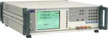
The 6430B and 6440B Precision Component Analyzers provide thorough and accurate testing of any passive component to high resolution. In particular, for capacitor manufacturers, the instruments provide capabilities for both fast automatic production testing and complete design characterisation. Users include designers of passive components, manufacturing test, designing and testing materials as well as circuit designers who are evaluating component characteristics. The resonant frequency can be automatically calculated for any component together with its equivalent series or parallel circuit at that frequency. Both instruments are designed for high performance testing of components, with a basic accuracy of 0.02%, at a low price. 6430B is the entry level instrument covering to 500 kHz whilst the fully featured 6440B covers to 3 MHz. To evaluate a component performance at high speed over a specified range of frequencies, multi frequency mode is used. In this mode the operator decides which parameter is to be measured and at what frequencies. The 6430B and 6440B does the rest, creating an easy to read table on the large LCD display. Each test can have a simple Pass/Fail display. Measurement parameters Impedance
(Z) Graphical sweep on all measurement functions up to 3 MHzTo characterize a component graphically the user can select any of the available measurement functions and create a graph of the parameter value against frequency or AC drive level. The user is also able to toggle between the major and minor term, for example impedance and phase angle. Either linear or logarithmic scales can be selected. Following the first sweep the user can use the FIT key, which automatically scales the vertical axis to provide the optimum display for the device under test (DUT). A marker is also displayed which can be positioned at any point on the graph using the navigation keys. The MAX and MIN keys position the marker at the peak or trough of the graph. The marker position is displayed at the bottom of the screen showing the vertical axis value, its minor term and the frequency or drive level. Printing results and external controlWhether its a single parameter, table of results from multi frequency mode or a logarithmic graph of component performance, the 6430B and 6440B will output the results directly to a printer. The GPIB interface is used to control the instrument and read back measured values for quality control or for archiving purposes. Output lines are also available to control a bin handler interface. Component tolerance levels may be pre-set and stored. A 25-way D connector mounted on the rear panel gives easy access for connection to external component handling equipment. Fast automatic multi-frequency production testing of capacitorsThe 6430B and 6440B deliver fast automatic testing of capacitors in a production environment. The user is able to select measurements from any of the instruments range and perform up to eight different tests on each component. Tolerance bins can be selected for each of the tests. The instrument selects the overall bin after completing all the tests. The measured results can be output over the GPIB or to a printer. The test sequence is triggered by external input, GPIB or the front panel. Once the test sequence is complete the bin is selected and the measured data is made available on the GPIB. This process takes place at very high speed allowing a dual frequency test to be completed in approximately 180 ms. Pass/Fail data in statistical form is available to the user and can be viewed on the LCD display, printed to a local printer or exported over the GPIB. Excellent performance and unbeatable priceAs the market leader with over 50 years experience of developing component analyzers you would expect Wayne Kerr to provide the best performance in the industry. However, what you might not also expect is that Wayne Kerr is able to offer high performance and accuracy at very competitive prices. Protection against charged capacitors
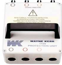
Overload Protection Unit 1J1100 High precision measuring instruments can be sensitive to charged capacitors and if connected can lead to costly repairs and unacceptable downtime. Wayne Kerr Electronics have identified this problem and developed a solution that protects the test equipment from charged capacitors. In this event, the protection unit blows fuses, which can be easily and cheaply replaced, whilst the test equipment remains unharmed and continues to provide reliable accurate performance. The protection unit will protect the test equipment from up to 25 Joules of charged energy. Technical SpecificationsMeasurement parametersAny of the following parameters can be measured and displayed:Inductance (L), impedance (Z), DC resistance (Rdc) and capacitance (C) Series or Parallel Equivalent Circuit C+R, C+D, C+Q, L+R, L+Q Series equivalent circuit only X+R, X+D, X+Q Parallel equivalent circuit only C+G, B+G, B+D, B+Q Polar Form Z + Phase Angle, Y + Phase Angle Test conditionsFrequency range 6430B20 Hz to 500 kHz > 1000 steps ( >1500 steps with analysis option fitted)Accuracy of set frequency ±0.005% Frequency range 6440B20 Hz to 3 MHz > 1800 stepsAccuracy of set frequency ±0.005% Pre-set frequencies20, 25, 30, 40, 50, 60, 80, 100, 120, 150 repeats for each decadeDrive level (Rdc)100 mV or 1 V with 100 Ω source resistanceDrive level (AC measurements)Open circuit voltage 1 mV to 10 V rmsSignal source impedance 50 Ω Automatic Level Control (ALC) maintains constant voltage or current at DUT DC bias voltage (internal)2 V with rapid charge capacitor biasDC bias voltage (external)External supply of up to ±60 V may be connected via rear panelMeasurement speedsFour selectable speeds for all measurement functions.Up to 20 measurements per second for test frequencies ≥100 Hz Measurement rangesR, Z 0.01 mΩ to > 2 GΩG, Y 1 nS to > 2 kS L 0.1 nH to > 2 kH C 1 fF to > 1 F D 0.00001 to >1000 Q 0.00001 to >1000 Rdc 0.1 mΩ to > 10 MΩ Basic accuracyL/C ±0.05%R ±0.02% Q ± 0.05 %(Q + 1/Q) D ±0.0002(1+ D2) Rdc ± 0.1% Accuracy varies with component range measurement speed and frequency Modes of operationMeasurementSelection of any measurement parameter and test conditionSingle level function menu controlled by keyboard and soft keys Single and repetitive measurements displaying major and minor terms DeviationAs measurement mode but relative or percentage deviation from nominal value displayed for major or minor termMulti-frequencyMeasurement parameters and test conditions set using measurement modeUp to 8 frequencies with absolute or percentage limits on major term Pass/Fail indication Multi-frequency capacitor (optional)Test condition set using measurement mode.Up to 8 frequencies with different measurement parameters. Binning result in up to 10 bins with percentage limits on major term and absolute on minor. Fast mode up to twice the speed of standard multi-frequency mode. Analysis mode (optional 6430B)Measurements parameters and test conditions set using measurement modeGraphical sweep vs. frequency or level with selection of start, step size, units and linear/log. Binning (optional)Measurement parameters and test conditions set using measurement mode.10 bins with absolute and percentage limits. Up to 99 sets of limits may be saved. 25 way D-type interface connector. Option /B1 (non-isolated)Common 0 V. Bin outputs 0 to 5 V(nominal) with >10 mA current sink capability.Option /B2 (isolated)Common 24 V input. Outputs 0 to 24 V with >10 mA current source capability.Measurement connections4 front panel BNC sockets4-wire (Kelvin) measurements with screen at ground potential GeneralPower requirements115 V or 230 V AC ±10% (selectable)150 VA Max Mains frequency50/60 HzMains fuse rating230 V operation - 1A T type115 V operation 2A T type DisplayHigh contrast monochrome LCD module320 x 240 with back lighting, Visible area 115 x 86 mm Viewing angle 45° Printer outputCentronics / parallel printer portRemote controlConforms with GPIB-IEEE 488.2 and SCPI 1992.0MechanicalHeight 150 mm (5.9″)Width 440 mm (17.37″) Depth 525 mm (20.5″) Weight 11 kg (24.25 lb) Environmental conditionsTemperature RangeStorage -40°C to 70°COperating 0°C to 40°C Full Accuracy 15°C to 35°C Relative humidityUp to 80% non-condensingAltitudeUp to 2000mInstallation categoryII in accordance with IEC664Pollution degree2 - mainly non-conductive This equipment is intended for indoor use only in a non-explosive and non-corrosive atmosphereSafetyComplies with the requirements of EN61010-1EMCComplies with EN61326 for emissions and immunityOrder codes and options
| ||||||||||||||||||||||||||||||||||||||||||||||||||||