Precision Magnetics Analyzer - 3260B | |||||||||||||||||||||||||||||||||||||||||||||||||||||||||||||||||||||
 |
| ||||||||||||||||||||||||||||||||||||||||||||||||||||||||||||||||||||
| Prospekt | |||||||||||||||||||||||||||||||||||||||||||||||||||||||||||||||||||||
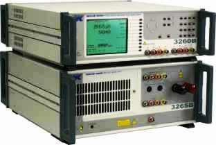
Completely characterize your components graphicallyAt the design stage of component development it is vitally important to understand how the component performs under different operating conditions. This might include operation at diverse frequencies, AC drive levels or DC bias currents. The 3260B Precision Magnetics Analyzer can plot any of the measurement functions, such as inductance (L) or impedance (Z), (including secondary term) against frequency, AC drive level or DC bias current. Frequency sweeps within the range 20 Hz to 3 MHz can be selected. There is a choice of either linear or logarithmic frequency displays. 3260B is especially suitable for measuring parameters on telecom transformers. The selected measurement parameter and its secondary value are presented graphically. AC drive levels can be set between 1 mV and 10 V. DC bias current can be set from 1 mA to 1 A internally. Using external 3265B 25 A DC Bias Units bias currents can be set to a maximum of 125 A. Measure Insertion Loss and Return Loss on telecom transformersWith the dramatic growth of PCs connected to the telephone system for Internet access has come the requirement to measure Insertion Loss (IL) and Return Loss (RL) of line matching transformers. The 3260B Precision Magnetics Analyzer not only measures IL and RL has this capability. but the instrument also allows the user to enter the values for terminating resistance or impedance, if complex, and to select a damped network or blocking capacitor if required. Specification summary
Printed output of test resultsUsing the parallel Centronics interface the user can directly print test results including graphs for further analysis and archiving. In addition, via the IEEE488 GPIB interface, the instrument can be controlled from a PC and results can be read back for analysis and storage. LabVIEW drivers are available upon request or may be downloaded from this website providing a base from which a user can develop a specific test application. Bin sortThe bin sorting function allows component manufacturers to sort components in up to ten bins. Sorting is carried out either by absolute values or by percentage of values. Component tests with up to 125 A DC bias current
3265B DC Bias Unit is used can deliver up to 25 A of DC bias current in steps of 0.025 A To evaluate components at high currents up to 125 A the optional 3265B DC Bias Unit is used. 25 A of DC bias current can be set in steps of 25 mA with one unit whilst up to five units can be used in parallel to give up to 125 A DC bias current. The standard 3260B Precision Magnetics Analyzer can provide an internal DC bias from 25 mA to 1 A. The 3265B has a number of safety and protection features including a safety interlock system to protect the user against back EMFs. It is also fully protected against over temperature,'excess voltage drop and sense lead failure. SMD inductor tests up to 50 A
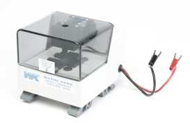
1009 DC Bias Fixture enables currents up to 50 A to be applied to an SMD inductor With the addition of the 1009 DC Bias Fixture DC bias currents up to 50 A can be applied to an SMD inductor during component test in order to evaluate the devices thoroughly at the operational bias currents. The fixture operates with one or two 3265B Wayne Kerr DC bias units and a 3260B Precision Magnetics Analyzer. Four rear panel mounted BNC connectors and two captive high current cables ensure simplicity and ease of use with the 3265B. Interchangeable component test carriers ensure that the 1009 DC Bias Fixture may be used with a wide variety of devices. If a device package is not supported by one of the standard carriers then a custom carrier design service is available. Stable component fixturing ensures high accuracy and repeatable measurements. Enclosed fixtures, with safety interlocks, minimises risk to operators. Technical SpecificationsOperation modesImpedance modeInductance (L), Impedance (Z), DC Resistance (Rdc) and Capacitance (C).Series or parallel equivalent circuit Loss term: Quality factor (Q), Dissipation factor (D), AC Resistance (Rac) and Phase Angle (Ø) Analogue scale (bar graph) with nominal, absolute and percentage% modes Handler modeEnables existing 4-wire scanners to be usedFunctions as for impedance mode plus Turns Ratio Transformer modeRdc of each winding, Primary or Secondary Leakage Inductance and Q, Turns Ratio, Interwinding Capacitance.Insulation between windings from either winding to screen/core is available as an option. Telecom modeProvides derivation of Insertion Loss (IL) and Return Loss (RL) for line matching transformers operating in the telephone speech band (100 Hz to 20 kHz). Values of line impedance (Zo) and termination (Rt) are user selectable. Optional simulated damping network and series blocking capacitor are user configurable.Analysis modeMeasurement parameters and test conditions set using measurement mode.Graphical sweep versus frequency, AC drive level or DC bias current with selection of start, stop, step size, units and linear/log. Multi-frequency modeMeasurement parameters and test conditions set using measurement mode. Up to eight frequencies with absolute or percentage limits on major term PASS/FAIL indications.Test conditionsLow level AC driveFor measurement of L + Q, Ls + Rs,C, Z, Turns Ratio and Leakage Inductance Frequency range20 Hz to 3 MHz inter winding capacitance, minimum frequency 1 kHzStepsIncrements of 1% or better across range with approximately 1800 frequencies.Accuracy of selected frequency ±0.01 % Drive levelSource impedance 50 Ω1 mV to 10 V rms into open circuit 50 µA to 200 mA rms into short circuit Automatic Level Control (ALC) maintains level applied to DUT at ±2%, ±1 mV of set voltage or ± 2% ±0.1 mA of set current. DC bias current1 mA to 1 A DC is available from internal, fast settling bias supply over full frequency range Voltage compliance 20 V minimumSafety interlock minimises operator exposure to high currents. DC resistanceLow test level of 100 mV minimises heating of the device under test.Short circuit current 10 mA Insulation (option)Test voltages of 100, 200 or 500 V DC, user selectableResults can be displayed as a current or resistance value Voltage accuracy ±3% For user safety, short circuit current is limited to <2 mA Bin Handler mode (option)Sort to 1 of 10 bins using absolute or percentage limits.Separate Pass/Fail output. Up to 100 bin limit set-ups stored in non-volatile memory. TTL interface to external bin handler via 25 way D type connector. Telecom mode (option)Drive level -28 to 16 dBmTest time varies with level Zo/Rt 50 to 2000 Ω Test time < 1.5 s typical Measurement speedsFor impedance, turns ratio, DC resistance and insulation4 speeds selectable: MAXimum, FAST, MEDium and SLOW MAX (20 measurements per second) is for component sorting under IEEE 488.2 remote control. FAST Approximately 10 measurements per second. SLOW Approximately 1 per second for increased stability and accuracy Measurement rangesR 0.01 mΩ to >2 GΩ*L 0.1 nH to >1000 H* C 5 fF to >1 F* AccuracyInductance/Rac/Z/Cp ±0.1 %**Q ±0.1% (Q+1/Q)** D ±0.001 (1+D2)** Turns ratio ±0.1 %** Rdc ±0.5 % Insulation ±5 % (500 V test) Insertion loss ±0.1 dB Return loss ±1 dB Basic accuracy varies with frequency, Zo, Rt, range and level. General dataInput specificationPower supply 230V AC ±10% or 115V AC ±10% (selectable) 50 to 400 Hz400 VA maximum consumption DisplayHigh contrast monochrome LCD 320 x 240 dot with CFL back lighting.Visible area 115 x 86mm. Viewing angle 45° Measurement connections8 front panel BNC sockets2- or 4-wire (Kelvin) measurements with screen at ground potential Equivalent circuit symbols on screen. Separate terminals for primary and secondary connections. LEDs indicate active terminals. Remote control (option)Conforms with to GPIB (IEEE488.2) and SCPI 1992.0Printer outputCentronics /parallel printer portAmbient conditionsOperating temperature range 0°C to 40°C.Full accuracy 15°C to 35°C SafetyComplies with the requirements of EN61010-1EMCComplies with EN50081-1, EN50082-1 generic emissions and immunity standards by meeting with the requirements of EN55022, IEC801.2, IEC801.3 and IEC801.4Mechanical (approx. overall)Height 150 mm (6")Width 440 mm (17 3/8") Depth 520 mm (20 1/2½") Weight 11 kg (24 lbs 4oz.) Order codes and options
| |||||||||||||||||||||||||||||||||||||||||||||||||||||||||||||||||||||